MFO-1
Multi-Function Oscilloscope MFO-1
The MFO-1 multi-function oscilloscope uses state-of-the-art analog electronics, digital and microprocessor circuits and advanced software to provide five instruments in one small, USB powered package: a 2-Channel, 2MSample/sec digital storage oscilloscope, a 200kHz arbitrary waveform generator, an 8 bit digital input-output port, a vector network analyser (Bode Plotter) and a digital spectrum analyser. With an intuitive and convenient user interface, the software is Open Source and runs under Windows, Mac and Linux operating systems.

Oscilloscope
The MFO-1 oscilloscope is a dual-channel, 2MSample/sec oscilloscope with 11 bit A/D conversion, digital storage and display.
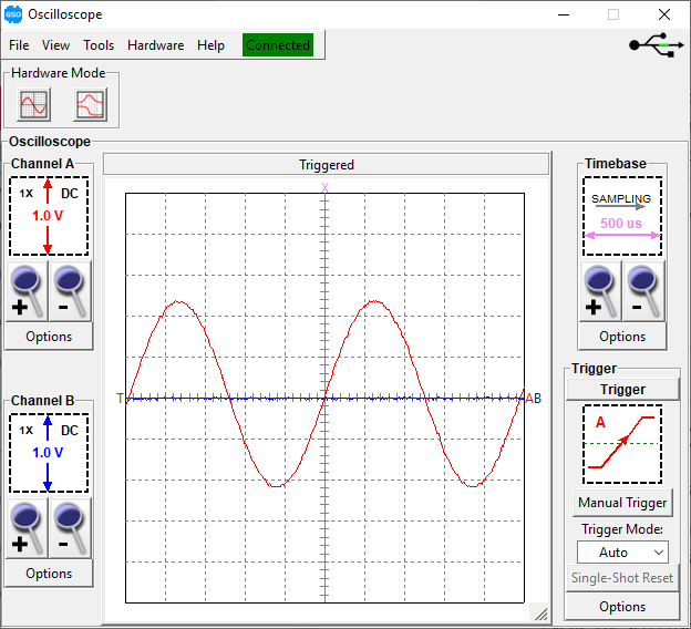
Channels A and B are sampled simultaneously and stored in the oscilloscope memory before being sent for display to the host computer. Triggering is accomplished by digital circuitry so it is precise and consistent. Trigger controls include Mode: Auto, Normal, Single-shot, Manual, Source: A or B, and Slope: Positive or Negative.
The time and level of the scope trigger point are continuously adjustable by on-screen cursors so that the operator can display the signal before and after the trigger event. The screenshot shows the on-screen cursors that are available to measure amplitude and time interval.
The graphical user interface has been designed to be intuitive with convenient access scope amplitude, timebase and trigger controls along with functions such as variable persistence, signal averaging, XY mode, math and instrument calibration.
Without digital averaging, the input noise is in the order of 5mV peak. On a repetitive signal with averaging the input noise is in the order of than 1mV peak.
For precision and stability the oscilloscope timebase frequency is derived from a crystal oscillator. The vertical preamplifier is gain-switched to optimize the signal-noise ratio and will accept x1, x10 and x100 scope probes.

Function Generator
The MFO-1 waveform generator is a powerful, general purpose signal generator with a user interface that makes it easy and convenient to use. All control settings are accessible from button and slider widget controls – there are no menus or sub-menus.
The Frequency control is particularly convenient, with a full range of 0.2Hz to 200kHz, linear or log characteristic. The operator can set lower and upper and frequency limits for the slider, such as 20Hz to 20kHz for audio testing. When precision is important, the operator can enter a frequency value directly.
The ability to set maximum and minimum frequency and the frequency output, to 0.1Hz resolution makes the generator useful for testing very narrow band filters or for finding resonance in an electromechanical system.
The Sine, Square, Triangle, Sawtooth and Noise waveforms are built-in. The operator can also create an arbitrary waveform.
The MFO-1 waveform generator has its own dedicated control panel and can be minimized when not in use. The amplitude and offset are implemented in hardware, so the output waveform is always a full 8 bits.
Arbitrary Waveform Generator
The MFO-1 waveform generator has the capability of generating an arbitrary waveform. For example, a car ignition waveform can be used for teaching purposes. An ECG waveform can be used to test a cardiac waveform filter. A SINC pulse can be used for impulse testing.
The operator creates the arbitrary waveform using the software tool we provide or a .csv file from a spreadsheet. The arbitrary waveform is a a simple sequence of 256, 8 bit values that can be provided in a text file.
The screenshot shows two cycles of an ECG arbitrary waveform.
As in the case of built-in waveforms, frequency control is available over full range of 0.2Hz to 200kHz. The operator can set lower and upper and frequency limits for the slider, such as 20Hz to 20kHz for audio testing. When precision is important, the operator can enter a frequency value directly. The amplitude and offset controls also adjust the arbitrary waveform.
The ability to set maximum and minimum frequency and the frequency output, to 0.2Hz resolution makes the generator useful for testing very narrow band filters or for finding resonance in an electro-mechanical system. The CGM-101 waveform generator has its own dedicated control panel and can be minimized when not in use. The amplitude and offset are implemented in hardware, so the output waveform is always a full 8 bits.

Digital I/O

On the electronic test bench it is often useful to control various digital signals, putting them in a high or low state as required. It’s also useful to have indicators to show the state of various digital signals.
The outputs can be controlled by SPDT switches and the inputs provided by LEDs. But this is inconvenient: switches bounce and LEDs require significant current, which may require driver transistors.
The MFO-1 digital I/O section eliminates the need to construct either of those circuits. There are 8 digital outputs that can be controlled from the user interface, and 8 digital indicators that show the state of some digital circuit. (The inputs are compatible with 3V and 5V logic.)
The rear panel connector is 10×2 places that mates with a ribbon cable, or you can socket test leads for individual connections.
In a student environment, these outputs and inputs can be used to manually control and display digital signals in a test circuit. For example, the digital IO outputs could be applied to the input of a logic gate, and the output of that gate displayed on an MFO-1digital IO input. A digital IO output could be used as a manual clock for a counter, and the output of the counter displayed on digital IO inputs.
The digital IO is particularly useful in connection with automatic test equipment. A designer can write software, using their preferred language and our Open Source API and source code, to send commands to the digital output lines and read the digital input lines. Combined with commands to read oscilloscope data and control the function generator output, it is possible to create an automatic test system at a very modest cost.
PWM Output
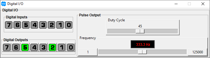
A pulse-width-modulated (PWM) signal is a two-level signal where the duty cycle is changed. PWM is the usual control signal for example in switching power supplies and high efficiency motor drives. Or it can be low pass filtered to provide an adjustable output voltage, thereby functioning as a simple D-A converter. The output voltagce is proportional to the average value of the waveform, which changes with duty cycle.
The duty cycle can be adjusted from 0 to 100%, and the frequency from 1Hz to 125kHz. The duty cycle remains fixed as the frequency is changed. (This is not true for some waveform generators, where the duty cycle changes with frequency.) Both the duty cycle and frequency can be adjusted by front panel controls and changed from the host via the software API.
Vector Network Analyzer
There are many electronic circuits where the amplitude and phase response are important: electronic filters, control systems, audio amplifiers and electro-mechanical systems such as guitar-pickups and loudspeakers.
The ability to measure the amplitude response over a range of frequencies is ‘Scalar Network Analysis’. The ability to measure both amplitude and phase over a range of frequencies, as in the MFO-1, is referred to as ‘Vector Network Analysis (VNA).
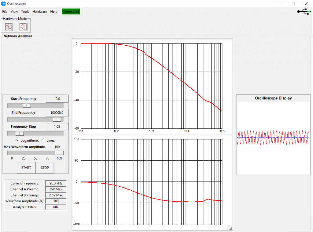
The amplitude and phase response can be determined point by point at individual frequencies by using the oscilloscope to measure the ratio of output vs input magnitude and phase. This is very tedious to do by hand. The MFO-1 automates this process, at a fraction of the cost of previous instruments. The frequency range is the same as the internal waveform generator: 0.2Hz to 200kHz. The amplitude range is in the order of 60db.
The screenshot shows the response of an RC filter circuit with a cut-off frequency of 350Hz. The plot confirms theory: the phase response passes through 45 degrees at 350Hz and the phase plot shows an attenuation of -3dB.
The VNA can ‘zoom in’ on a response, showing amplitude and phase details over a small frequency range.
In the classroom and development lab, the VNA eliminates the tedium of manual measurements and allows the operator to concentrate on the shape circuit frequency response. It is straightforward to relate component values to the actual behaviour of amplitude and phase, and compare that to the response predicted by simulation.
1. Overview
The GSD Electronics MFO-1 is five electronic test instruments in a compact package: a dual channel digital storage oscilloscope, a signal generator, a spectrum analyzer (bode plotter), a spectrum analyzer and a digital input/output interface.
The MFO-1 is a small, robust hardware module that connects to a PC via USB. The host software is open source.
1.1 Oscilloscope
The oscilloscope is a dual-channel, 2 MSample/sec oscilloscope with 12-bit A/D conversion, digital storage and display.
Both input channels are sample simultaneously and stored in the oscilloscope memory before being sent for display on the host computer. Consequently, the signals are always time aligned and associated with the same trigger signal. Triggering is accomplished by digital circuitry so it is precise and consistent. Trigger controls include Auto, Normal, Single-shot, and Manual modes, triggering from either channel and positive or negative slope. The time at which the trigger occurs is continuously adjustable by adjustment of an on-screen cursor so that the operator can display the signal before and/or after the trigger event.
The oscilloscope timebase frequency is derived from a crystal oscillator, so it can be expected to be precise and stable. The displayed amplitude is determined by 1% resistors and analog-digital conversion. The vertical preamplifier is gain-switched to optimize the signal-noise ratio and will accept x10 and x100 scope probes.
1.2 Waveform Generator
The waveform generator is a direct-digital synthesis (DDS) based device with frequency range between 0.1Hz and 200kHz with a frequency resolution of 0.1Hz. The frequency can be adjusted, without range switching, over that entire range or some part of that range.
The usual sine, square, triangle and sawtooth waveforms are supplied with the instrument. The generator can also load and produce an arbitrary waveform. A GUI-based program WaveMaker is available for the construction of arbitrary waveforms.
1.3 Digital I/O
The digital I/O section includes an 8 bit output port and 8 bit input port. Outputs are controlled by 8 GUI buttons. Inputs are displayed on 8 GUI indicators.
In addition, there is a pulse generator outputwhich is continuously variable over the frequency 1Hz to 125kHz, with continously adjustable duty cycle.
In combination, these controls form the basis for digital controls and displays for basic digital exercises or more advanced control systems.
1.4 Vector Network Analyzer
For automatic sweep, a Vector Network Analyser (VNA) (aka Bode Plotter) program is available. The VNA software operates the oscilloscope and generator sections in concert to sweep a network over a specified range and plot the amplitude and phase of the response.
1.5 Spectrum Analyzer
A frequency spectrum of the input signal can be shown at the same time as the time-domain waveform display on the oscilloscope screen. The spectrum display is generated by the Fast Fourier Transform algorithm, so that it responds instantaneously to changes in the input waveform. This is ideal for demonstrating the relationship of signals in the time and frequency domains.
1.6 General Hardware Information
The MFO-1 hardware is in a pocket-sized package that can easily be carried in a backpack or with a laptop computer. Power and control signals are provided to the hardware via a single serial-emulated USB connection with the host PC. An external power module (wall-wart) is not required.
The PC host displays a graphical user interface for the oscilloscope with frequency readouts, sliders, clickable buttons and various other controls. Each instrument appears in its own window: unused instruments can be minimized. The screen of the oscilloscope is resizeable.
The hardware is entirely controlled by software: there are no electro-mechanical switches or adjustments. This makes the hardware very reliable and supports development of custom control software in OEM applications.
The GUI software is written in the Tcl/Tk language. The software is open source and entirely in Tcl/Tk. The GUI software will operate under Windows, Linux, or Mac operating systems. Tcl/Tk is an open-source, interpreted language, so reading and modifying the source code is straightforward.
The applications programming interface (API) is documented, so the hardware can be accessed by other computer programs and languages. The only requirement is that the language be able to communicate with a serial (COM) port.
1.7 Software Updates and Help
The full manual is available online in this document.
The software checks the GSD website and advises if there is a new version of the software available. You can check manually by selecting Check for Update in the Help menu. Alternatively, you can configure the software to do that automatically every time it starts. Select the Check for Updates on Startup menu item.
The Change Log (record of changes with each version) is available as a Help menu item.
2. Additional Applications
In addition to the usual operation of oscilloscope and signal generator, here are some possible education applications of the MFO-1.
- Logic Net: The digital controls supply the functionality of a digital Exerciser Unit, which can apply a stimulus to a digital circuit and measure the output. For example, the 8 bit digital lines can be used as inputs and indicators for a logic net. Students set up various combinations of input signals to the net and record the outputs to generate logic equations or a truth table for the logic net.
- State Machine Exerciser: A single manual output line and the PWM output can be used as a pulser for counter and state machine circuits. The manual output exercises the circuit at low speeds, where the behaviour can be observed on the GUI indicators. The PWM output is then used to operate the circuit at higher frequencies, and the oscilloscope can be used to observe faster events.
- Mixed Analog and Digital Circuits: The digital outputs control a MDAC (multiplying D-A converter) which sets the centre frequency of a bandpass filter. The generator and oscilloscope function as a Vector Network Analyzer, showing how the frequency response changes as the digital value is adjusted.
- Switching Power Supply: The PWM output controls a power MOSFET and LC network which functions as a simple switching power supply. Similarly, PWM output can modulate the power to a DC motor as a simple method of speed control.
- PWM DAC: It is common for the PWM output of a microprocessor to be used as the basis for a low-cost digital-analog converter. The PWM signal is filtered to produce a variable analog control signal. In this exercise students design the PWM filter and then measure the ripple using the oscilloscope. They can also operate the PWM signal at various frequencies to illustrate the effect of frequency on ripple.
3. Features and Specifications
3.1 Oscilloscope
| Channels | 2 independent channels sampled simultaneously |
| Sampling Frequency | 2 MSamples/second maximum |
| Vertical Resolution | 12 bits per channel (1:4096) |
| Vertical Bandwidth | 200 kHz |
| Vertical Input Ranges | +/-250mV to +/-25V full scale |
| Vertical Gain Settings | 9 settings, 10mV/div to 5V/div in 1:2:5 sequence |
| Vertical Coupling | AC or DC coupling |
| Vertical Offset | Full screen, +/-20V max |
| Vertical Scale | 10 major divisions |
| Horizontal Time Settings, Timebase Mode | 17 settings in 1:2:5 sequence 500 ns/div to 100 ms/div |
| Horizontal Time Settings, Strip Chart Mode | 7 settings in 1:2:5 sequence 200 ms/div to 20 s/div |
| Horizontal Scale | 10 major divisions |
| Input Impedance | 1MΩ || 27pF |
| Triggering | Analog compare with input signal |
| Trigger View | Pre and post trigger with adjustable viewing window |
| Trigger Controls | Source (A, B, manual), adjustable trigger level, slope select |
| External Trigger Out | Rear panel connection, logic level output |
| External Trigger In | Rear panel connection, logic level input |
| Memory Depth | 1k samples per channel |
| Additional Software Features | Cursor Readouts Spectrum Analysis X-Y Plot Data record to CSV Save/restore settings Auto measurements Vertical Calibration Offset Calibration |
3.2 Waveform Generator
| Frequency Range | 0.1 Hz to 200kHz |
| Output Waveform Amplitude Range | +/-2.5V |
| Amplitude Control | Hardware, 12 bit |
| Output Offset Range | +/-2.5V |
| Offset Control | Hardware, 12-bit |
| Vertical Waveform Resolution | 8 bits independent of amplitude and offset |
| Output Impedance | 150Ω |
| Waveforms | Sine, square, triangle, ramp, arbitrary |
| Arbitrary Waveform | 8-bit vertical resolution 8-bit horizontal (256 samples) Software waveform editor |
3.3 Digital I/O
| Input | 8 bits Software indicators 3-5V HCMOS |
| Ouput | 8 bits Software controlled via buttons 5V HCMOS |
| Pulse Output | Variable frequency, 1Hz to 125kHz 1Hz frequency resolution Variable duty cycle, 0 to 100%, 1% resolution |
3.4 Physical
| Housing | Aluminum, anodized |
| Indicators | Power LED (Green) Activity LED (Yellow) |
| Interface | USB2.0 |
| Dimensions | Length: 112mm Width: 114mm Height: 35mm |
| Software | Windows, Linux, OSX Written in Tcl/Tk Open source |
| Power Consumption | <2.5W |